
EE453 E-Bike Power Electronics System Design
For this project, Ishaan Bhimani and I designed the power electronics hardware and controls to convert power from a 24V battery to an AC waveform that controls the BLDC motor of an E-bike.

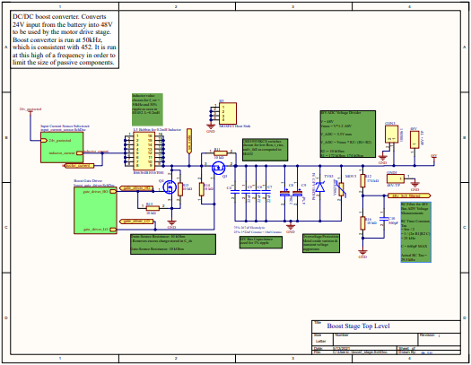
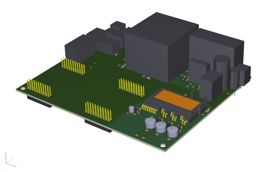
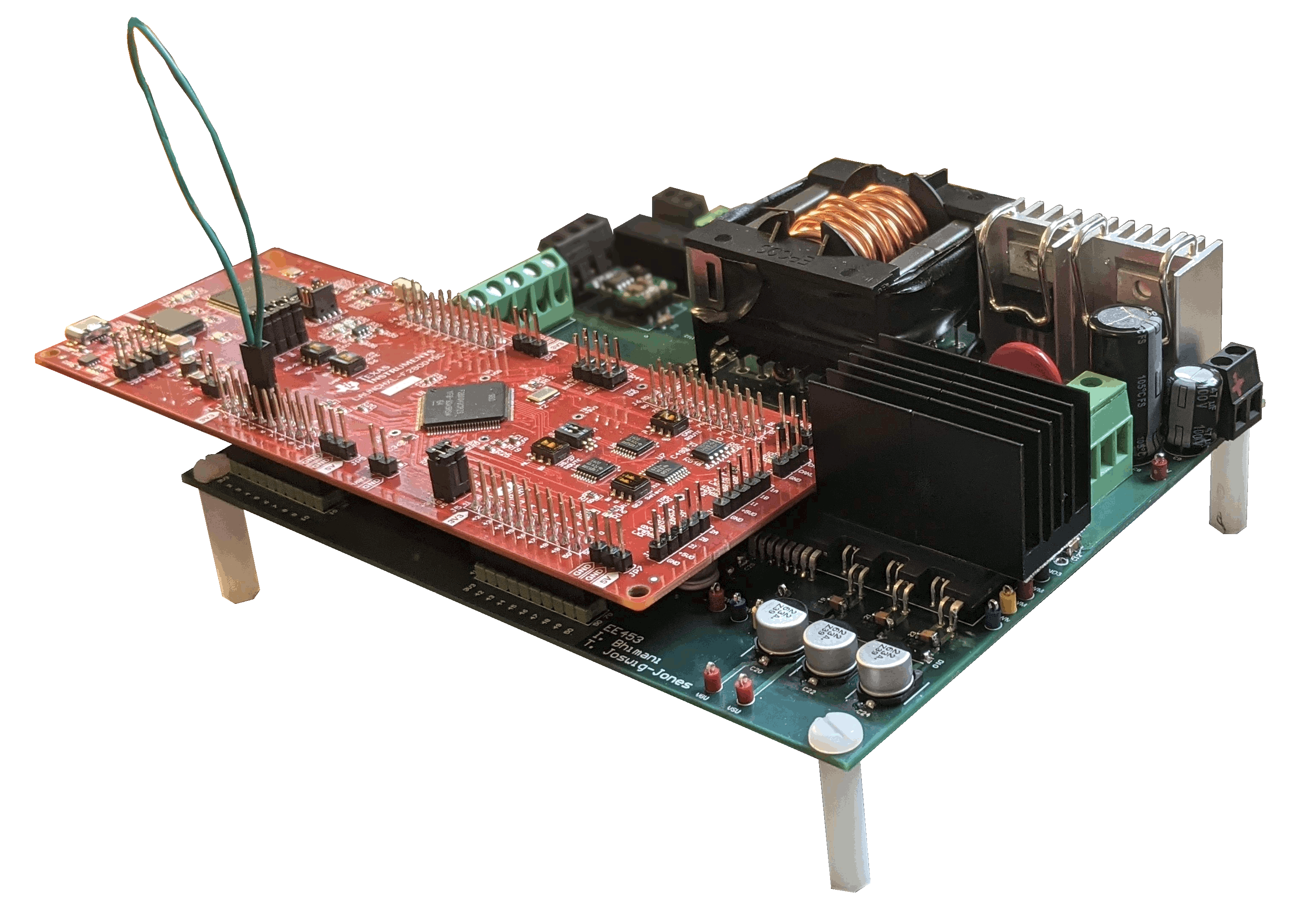
The process of designing and building this system included creating electrical schematics, fabricating a PCB, developing digital signal processor controls, and testing the integrated control system with a resistive load.
Our boost converter was able to successfully boost the 24V input voltage to 48V and track a reference voltage using a PI control with an inner current loop and an outer voltage loop. With the output of the boost converter feeding the 3-phase H-bridge inverter we tested open loop motor drive control on a wye connected resistive load, due to lab access restrictions during the COVID-19 pandemic. Waveforms of this testing can be seen below.
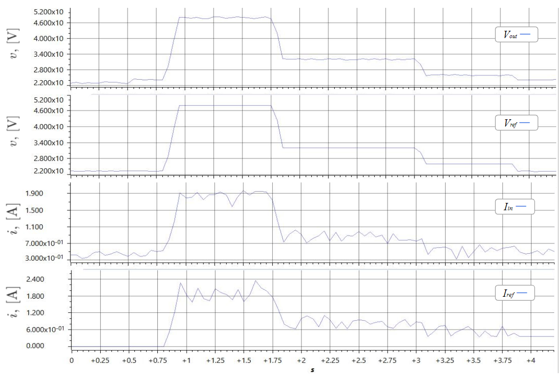
Boost stage 48V reference voltage closed-loop control test waveforms.
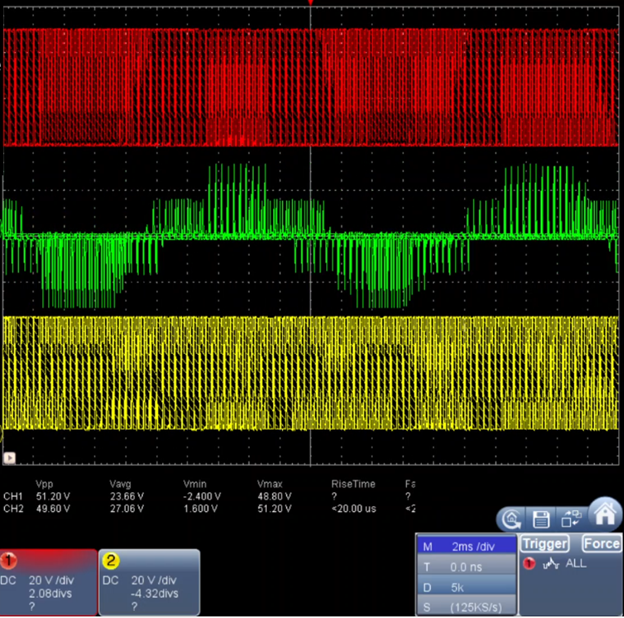
LN inverter output voltages.
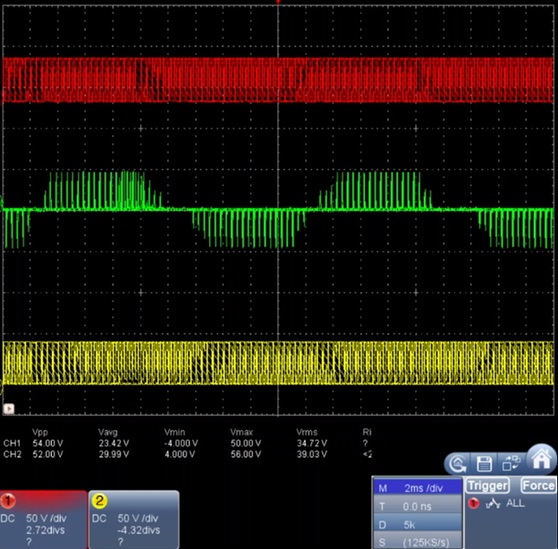
LL inverter output voltages.